Today I stripped the floorboards today and was surprised how good they actually looked. They have a couple of broken tongues, a couple of cracks and a little trimming needed but that is all easy to fix.
More later.
The Begining This car was bought, some years ago, from Gullwing Motors in New York. It was an older restoration at that time, as far as I can ascertain. The car was found in a barn in north Florida ten or more years ago and went through two avid Morgan owners, being dismantled by the second one and then passed on to me. Much work had been done including a new chassis as well as quite a collection of new parts. Here is what I bought.
Tuesday, June 25, 2019
Sunday, June 23, 2019
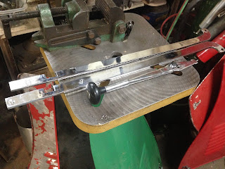
GEARSHIFT REPAIR
The gearshift had some problems. The center plate that provides the neutral slot was badly worn and allowed a lot of slop.
I decided to weld it up rather than make a new one.
The next problem was the shift lever pivot pin. It was badly worn and the fix was easy. I turned down the 3/8" part to the 5/16" thread size and made a sleeve to slide onto the bolt.
One of the shift rails had an oversize slot too but I don't think that will matter. The next problem was that the 2nd gear shift would over ride the detent and continue further. This allowed the bottom of the shift lever to come out of the slot in the shift rail. The stop pin in the shift rail was in the wrong place so I added another one just next to the original one. This was an easy fix and now it shifts well. I am awaiting the new Thackery spring washers to arrive and this will all be done. Someone in the past chrome plated the shift lever and the shift rails.
The Thackery washers came in today so now it's all finished up.
Friday, June 21, 2019
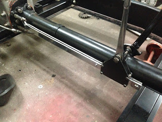
FRONT CHASSIS TIE RODS
The front plates, if I can call them that, have a hole at the bottom to accept the diagonal tie rods. on this car the holes are of an odd upside down triangle. Someone, long ago, had made some thin plates that covered the holes with the tierod coming through in order to tighten it all up. The plates had a half round notch on the bottom to fit against the bottom crosstube. I guess the thinking was that the car weight would push the plates down and limit their motion. Backwards thinking.
I ended up making a special shoulder washer to fit the opening and allow the nut to tighten and do some good.
This worked great after some fiddling.
I ended up making a special shoulder washer to fit the opening and allow the nut to tighten and do some good.
This worked great after some fiddling.
Thursday, June 20, 2019
ROLLING CHASSIS!!!!!
With all that done, all I needed to do was mount the 3 wheels. The front brakes are hydraulic and have odd wheel bolts and I could not find wheel nuts to fit so I ordered a 1/2BSF tap and made the nuts. I made them from a high alloy bronze hex bar that I had on hand. This is tough stuff with a high shear strength so I have no worries about using it. I milled the hex to match the 9/16" nuts on the rear hub.
Once this was all buttoned up the chassis hit the ground for the first time in over 5 years. Exciting day.
Once this was all buttoned up the chassis hit the ground for the first time in over 5 years. Exciting day.
GEARBOX MOUNTING
Now to mount the gearbox. This car has a twin gearbox which is the same internally but the bottom mounting bosses are of a different height and angle requiring making some special shims. I set the gearbox in place and bolted the torque tube to it and to the front crossmember. Using feeler gauges i was able to determine the thickness at the front and back edges of the bosses. Then it was an easy machining job to make a tapered shim for the front and rear mounting spots.
I did this on a tilt table mounted on the mill table. I could adjust the tilt angle by using a dial indicator and reading across the plate until I got the difference in thickness I needed for the angle needed. The tilt table is not very wide so I had to shift my hold down bolts and do it half at a time.
Here is a view of the installed shims.
The Chassis
The chassis was built new by the previous owner so i have a good basis to build from. The gearbox was in very good condition and only needed new cross shaft bearings and some trunnion work.
TRUNNION REPAIR
The trunnion/fork fit should be within .001" but mine was .015" on one side and was way too loose. The fork needed to be trued and the trunnion had to be turned and have a sleeve fitted. Fork truing was an easy milling machine job using a boring head.
The trunnion was held in the lathe and turned down. I found that this had already been done once before. As I was turning the surface down I found this.
I finished turning this down and then machined a sleeve to fit.
Usually the sleeve is soft soldered to the trunnion but I chose to use LocTite bearing mount. It looks like the previous job was done that way and had no problems. Here you can see the outer race for the roller bearing. It looked like it should be replaced as you can see.
Here is the finished product. I also plan to add a Fork Reinforcement of some sort.
Subscribe to:
Comments (Atom)


